ICOM IC-746
Backlight Repair Page
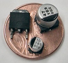
CAUTION! Repairing the IC-746 backlight involves working with surface mount components. Due to the extremely small size of these components and the delicate nature of the circuit boards, do not attempt this modification unless you are experienced in surface mount repair and have the proper equipment. YOU CAN EASILY DAMAGE YOUR RIG IF YOU DO NOT HEED THIS WARNING! Photo at left shows actual components on a penny for scale. Many Icom IC-746's suffer from intermittent or non-functioning LCD backlights. Although Icom's service department pretends these failures are rare, a quick internet search reveals otherwise. Early symptoms of backlight problems include delayed turn on, random changes in brightness, and reduced maximum brightness. Eventually, the backlight may begin to randomly switch on and off, operate at drastically reduced brightness, or fail completely. Without the backlight, the LCD is virtually unreadable. These problems appear to be caused by a failure in backlight power supply inverter. The schematic above shows the inverter circuit for the 746's cold cathode lamp, and the arrows indicate the parts I replaced. Q302 acts as a pass transistor, regulating the current flowing to the transformer and switching transistors Q303 and Q304. This varies the transformer's secondary voltage, and the lamp brightness. Capacitors C302 and C303 serve as filter caps and help smooth out the current peaks rushing thru Q302 as the switching transistors turn on and off. The photo below shows the S LOGIC BOARD after being removed from the transceiver front panel. The arrow points to the location of the inverter assembly (white outline on PCB) after it's shielded enclosure was removed from the circuit board.
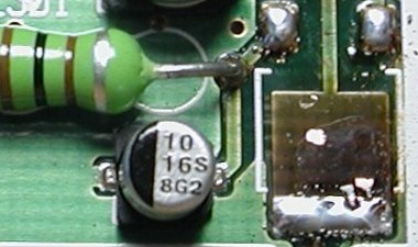
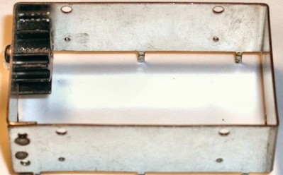
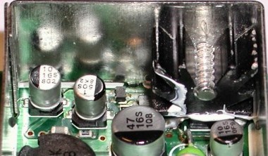
The inverter circuit is shown below. In the photo on the left, arrows point to the location of the three components I replaced. The photo on the right shows a close-up of the printed circuit board after transistor Q302 was removed. Discoloration of the board from excessive heat is clearly visible. It was obvious to that Q302 was getting too hot. I have seen similar problems in VCR's, many of which use a small inverter module to generate the high voltage needed by the fluorescent clock displays. A common failure mode occured when heat from the inverter module began drying out the near-by input and output filter capacitors. As their values dropped, the peak current passing through the inverter increased, creating a viscious self-destruct cycle. Not having a capacitance meter handy, I decided to change both C302 and C303 just to be on the safe side, as their physical proximity to Q302 made it a pretty safe bet they had been exposed to elevated temperatures. However, I wasn't satisfied with just fixing the problem. I wanted to make sure it never came back to haunt me again! It was obvious that Q302 suffered from poor design and/or layout, and needed some type of heat sink. Why ICOM didn't just use a PWM regulator to vary the duty cycle of the switching transistors is beyond me! After scrounging thru my junk box, I found an old heat sink with a TO-220 transistor still attached to it. As shown in the left photo below, I used a hacksaw to cut off a small part of the finned side. Then I filed down the small piece till it was just the right size to fit over Q302. The inverter shield was then temporarily re-installed on the PCB, and the location for the heat sink mounting screw hole was transferred the shield wall. The shield was removed and then drilled. The hole was intentionally offset a few thousandths of an inch down toward the circuit board. This guarantees the heat sink makes contact with the transistor before the shield bottoms out against the circuit board, promoting good heat transfer. The right photo below shows the heat sink attached to the inverter shield. Once the heat sink was screwed to the shield, the assembly was test fitted before final assembly. Thermal compound was applied to the heatsink, and the shield was installed and soldered back in place on the PCB. The photos below show the completed repair, with the home made heatsink installed over the new Q302, next to the replaced C302 and C303. The only problem encountered in final assembly was a clearance issue involving the screw head for the heatsink, which ended up butting against the contacts for the M CHANNEL encoder. This issue was addressed by filing down 50% of the screw head, trimming the excess lead length protruding through the encoder PCB, and then sticking a piece of electrical tape over the screw head side of the shield assembly, just for good measure! For anyone who feels brave enough to attempt this at home, the offending parts are located on the S LOGIC BOARD and have the following ICOM part numbers: Q302, P/N 1520002060; C302, P/N 4510004630; C303, P/N 4510004640. Since manufacturers may change part numbers from time to time, there is no guarantee the above numbers are still good. Play it safe and verify the correct part numbers before placing an order. Part numbers can be found in the IC-746 service manual. SUCCESS! Once radio was put back together, the backlight (and everything else) worked fine! If the inverter circuit is a weak link, why don't they all fail? I think it's a pretty safe bet to assume the backlight brightness setting has a lot to do with it. I used to keep mine set at 50% to maximize tube life. However, Q302 has to dissipate more power at the 50% setting than at the 100% setting. Since power dissipation = heat, I think this practice may have contributed significantly to the failure of Q302. 


